Push Button Battery Isolator Wiring Diagram

Ke 5002 Wiring Diagram Together With Boat Dual Battery Switch
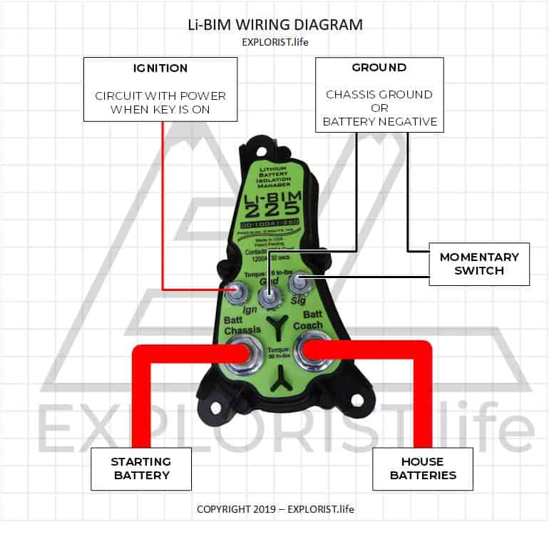
How To Wire An Li Bim Lithium Battery Isolator Explorist Life

Connecting A Leisure Battery To A Car Battery Wiring Diagram

The Ultimate Dual Battery Setup Redarc Electronics

19mm 22mm Billet Automotive Buttons Wiring Diagram Video Rgb

5 Pin Momentary Switch Wiring Diagram With Images Switch Wire
Each part ought to be set and linked to different parts in specific.
Push button battery isolator wiring diagram. Boat battery switch wiring diagram boat battery disconnect switch wiring diagram boat battery isolator switch wiring diagram boat battery selector switch wiring diagram every electrical arrangement consists of various different parts. Start assist feature optional. Also this can be used as a guide if you want to re. Typical push buttons are momentary meaning they are designed with a spring to keep the button contacts open or closed at all times.
Automotive 4 pin and 5 pin relay explained which one. To manually operate the smart start sbi hold the. Heres a complete guide to wire up a kill switch so you can race at the track if your battery is relocated. The li bim is a battery isolator specifically designed to work with lithium house batteries.
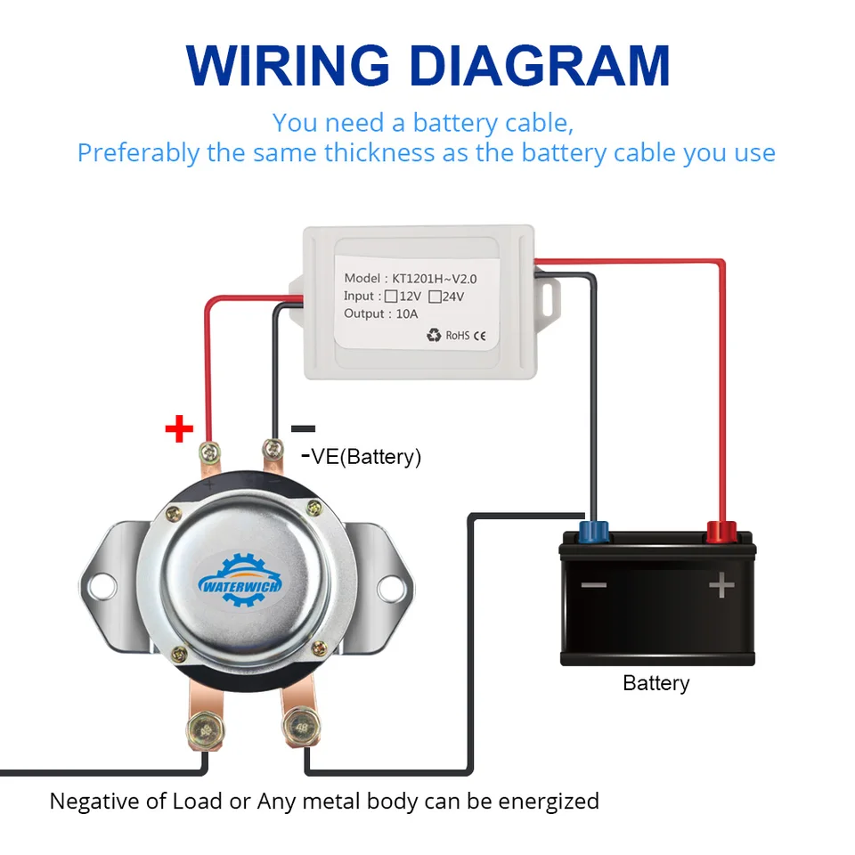
The battery isolators work by being fitted in between the negative side of the battery and the chassis as seen above. Start stop push button wiring diagram emergency stop push button wiring diagram start stop push button station wiring diagram start stop push button switch wiring diagram every electrical structure consists of various different parts. Each part should be placed and connected with other parts in particular way. Continuous duty solenoid relay wiring diagram when we think of relays we tend to think of those big mechanical it at higher currents or extended periods of time my mains wiring does not include an electrical ground description family of safety relays for the interfacing of one integrated light curtain equipped with the edm external device monitoring function that is of the series eos4 x.
Luxe performance 1 452 views. Race car how to wire and use 6 pole battery isolator kill switches duration. The standard agm tuned isolator will see this higher voltage as a charging voltage and will not disconnect the starting and house batteries which means the starting. Lithium batteries like battle born batteries have a slightly higher resting voltage than their agm or lead acid counterparts.
Proper battery management including switching and charging is essential for safe and reliable operation. Connect the other terminal of the momentary push button switch to the auxiliary battery supply. Almost all industrial machines contain push buttons even if the facilities operation is to set to run automatically. Push buttons shown in figure 1 are the most common type of control devices found in industrial facilities.
On the dash as specifi ed in the diagram on page 3. The following basic wiring diagrams show how batteries battery switches and automatic charging relays are wired together from a simple single battery single engine configuration to a two engine one generator and four battery bank system.

Battery Isolators And Automatic Charging Relays Blue Sea Systems

How To Wire Bms1230s2 From Caravan To Vehicle With Variable
Wireless Remote Control 12v 24v Isolator Battery Disconnect Car

Ml Acr Automatic Charging Relay With Manual Control 12v Dc 500a

How To Wire A Push Button Start Diagram Yahoo Image Search
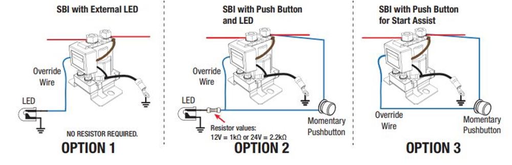
Redarc Smart Start Battery Isolator With Wiring Kit 12 Volt

95 Amp 1 Input 2 Output Multi Battery Isolator Sure Power
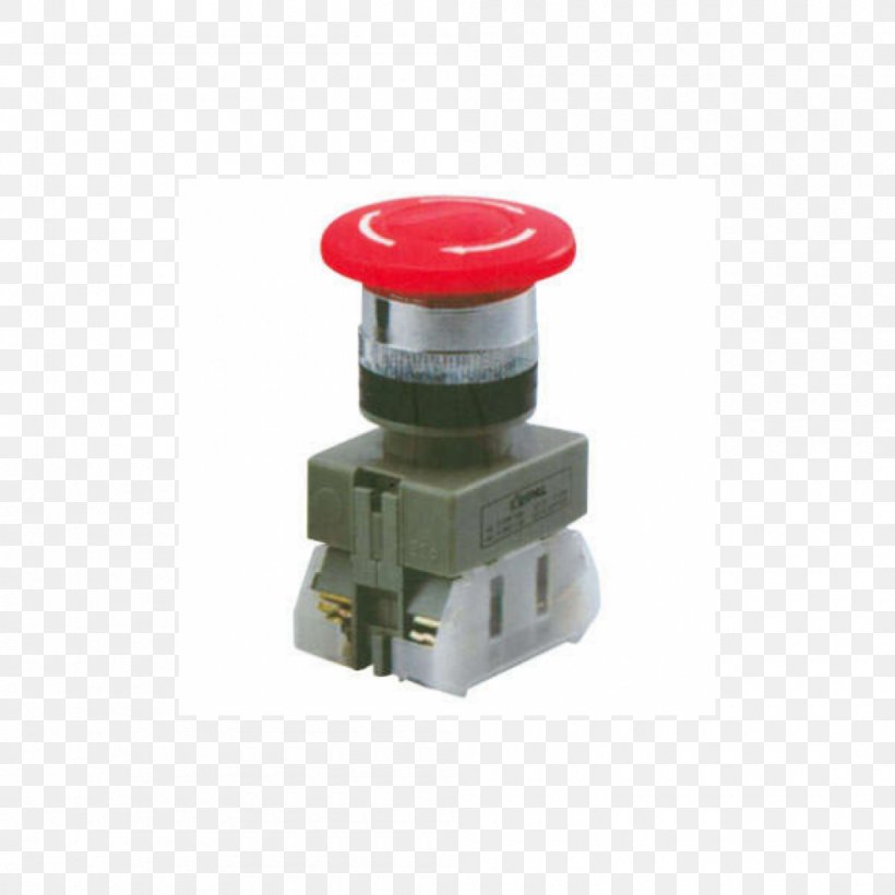
Car Kill Switch Push Button Electrical Switches Png 1000x1000px
