Pump Control Box Wiring Diagram Adjustment Settings

Submersible Pump Control Box Wiring Diagram For 3 Wire Single

The 21 Best Wiring Diagram Creator Electrical Circuit Diagram

Single Phase Submersible Pump Starter Wiring Diagram On Water

Automatic Water Pump Control Testing Youtube
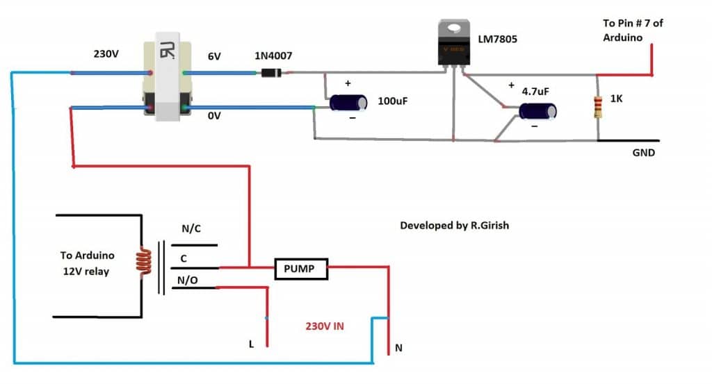
Gsm Pump Motor Controller Circuit Using Arduino Homemade Circuit

Models 3 To 7 5hp 7 5 To 10 Hp Specifications Auto Start Unit

How to adjust a shallow well jet pump pressure switch.
Pump control box wiring diagram adjustment settings. 3 wire motor installation options. The wiring diagram identifies the electrical terminals and lists their functions. Later when i get the simple pump fixed and mounted through. Chris walks you through the most important things to consider when selecting a pump control panel.
To 2 wire motor or 3 wire control box alarm contacts figure 3. Additionally the munro smartbox provides personal protection. I ended up for now simply mounting all the control components to the coupling on the well casing and covering it with a plastic barrel. This article describes how to adjust building water pressure by setting the water pump cut in and cut out pressure on the well water pump pressure control switch.
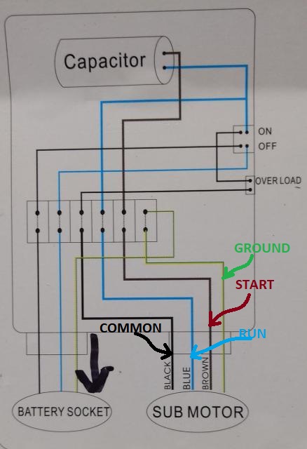
If you need more information or assistance with products call 855 329 4519 or email customer. Single phase submersible pump control box wiring diagram 3 wire submersible pump wiring diagram in submersible pump control box we use a capacitor a resit able thermal overload and dpst switch double pole single throw. Septic pump wiring wholesale septic supply. Smartbox standard the old stand by a great option for pump start and pump protection in one the munro smartbox includes a preset pressure sensor that alerts the control system of potential pump damage due to loss of prime or run dry.
A complete guide about single phase submersible motor starter wiring diagram explanation or single phase 3 wire submersible pump box wiring diagram in english video tutorial. How to wire an orenco s series control panel duration. Inspect the control box s wiring diagram located on the back of the lid. Set the time out adjustment to the desired position.
The factory underload setting of 70 should not require. The factory setting is 30 minutes see figure 4. Pressure switch for well pu. A wire set from the storage tank s pressure switch and a wire set that leads to the pump motor enters the control box.
Control box control box pump motor l1 l2 gnd l1 l2 gnd figure 2b.
Water Pump Wiring Troubleshooting Repair Pump Wiring Diagrams

Tweeter Crossover Circuit With Diagram To Filter Low Frequency

Rotax Ist System 2016 Inr Wiring Diagram 89 Diagrams Motor T With
12v Dc Motor Speed Control Circuit Diagram Motor Speed Circuit
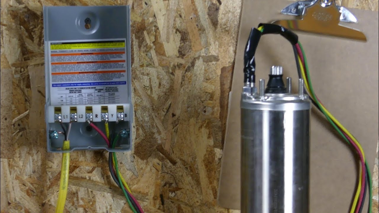
How To Wire A Franklin Electric Qd Control Box 1 3 1 Hp Youtube
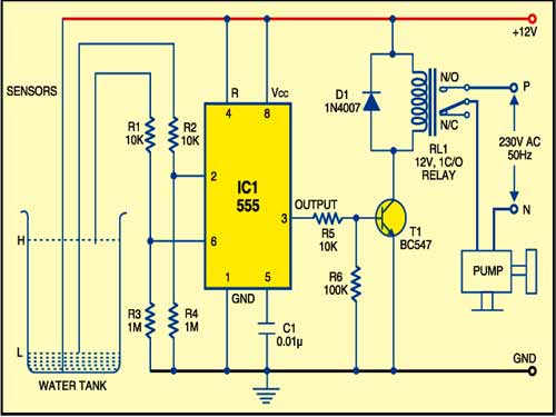
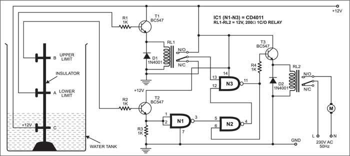
Water Pump Controller Detailed Circuit Diagram Available

How To Wire A Bilge Pump With Images Boat Wiring Trailer
Automatic Water Pump Controller Full Circuit Available
